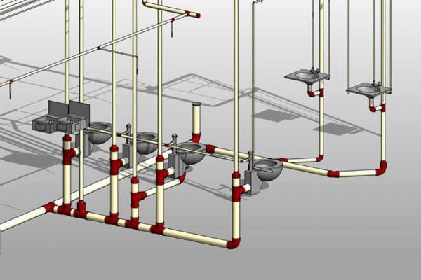
Understanding the Various Classifications of MEP Drawings in Construction

Strong 8k brings an ultra-HD IPTV experience to your living room and your pocket.
In the construction universe, MEP (Mechanical, Electrical, and Plumbing) drawings are elemental to avoid threats that might thwart the full achievement of projects. These detailed plans create a directional map and lead to the readily embarked upon installment and integration of the basic building systems. In this blog entry, we'll narrate the diverse categories of MEP drawings and how they contribute in the construction industry.
The Importance of Accurate MEP Drawings
Before getting even into the MEP drawings' types let me explain to you first what their influence is on projects of construction. Accurate and well-designed MEP drawings are critical for several reasons: Accurate and well-designed MEP BIM drawings in Construction are critical for several reasons:
Efficient Project Execution: The MEP drawings are a guideline followed by contractors, allowing all the electrical, mechanical, and plumbing systems to be put into place correctly and in accord with the construction project's standards.
Cost Savings: Through showing the necessary points for the building and reducing the possibility of mistakes causing reworks, delays, and material wasting, they contribute to saving money.
Seamless Coordination: MEP drawings enhance communication among different trades, most notably technicians for heating, ventilation, and air conditioning, electricians, and plumbers, which aim at having their jobs properly coordinated to avert conflicts and work-related accidents.
Classification of MEP Drawings
Next, it is the time when we will uncover the varied types of mechanical and electrical (MEP) drawings and their individual functions on a building project.
Mechanical Drawings
Mechanical drawings, as a basic structure, address the points of installation and design of HVAC system including mechanical, ventilation, and air conditioning (HVAC) systems. These drawings include:
- Ductwork layouts
- Equipment specifications
- Piping diagrams
- Temperature control systems
Mechanical blueprints check that the systems of HVAC are built according to the specified version of the building to provide residents with excellent comfort and the energy efficiency they need.
Electrical Drawings
Electric diagrams should include the design and composition of power distribution, lighting, and communication systems inside a construction site. These drawings include:
- Wiring diagrams
- Lighting layouts
- Power outlet locations
- Electrical panel schedules
Accurate electrical drawings are a must when it comes to safety and efficient working of electrical system which is of prime importance in a building.
Plumbing Drawings
Local drawings first provide design and placement of water supply, drainage, and sewage systems. These drawings include:
- Piping layouts
- Fixture locations
- Drainage plans
- Riser diagrams
Top-quality plumbing drawings are of importance because they make a building water conservation and features intended to avoid future leaks and blockages.
Fire Protection Drawings
The fire protection drawings are intended as a design guide to illustrate the way the various fire suppression systems, including sprinklers and fire alarms, are installed. These drawings include:
- Sprinkler head locations
- Fire alarm system layouts
- Evacuation plans
- Fire-rated construction details
Precise fire alarm blueprints are critical for provisions safety of building residents and as well for observance of regional fire code and regulation.
Best Practices for Creating MEP Drawings
To create effective and accurate MEP drawings, professionals in the construction industry should follow these best practices:To create effective and accurate MEP drawings, professionals in the construction industry should follow these best practices:
Collaborate with Other Disciplines: Work side by side with the architecture firms, structural engineers and any of the other stakeholders to make sure the MEP (mechanical, electrical, plumbing) drawings are well-coordinated and in alignment with rest of the project’s design.
Use Standardized Symbols and Notations: Make use of the industry standards symbols and notations in order to make sure that the correct symbols and entities are used across all arrows and MEP drawings for the sake of clarity and consistency.
Leverage Technology: Employ to the most up-to-date software platforms, like Building Information Modeling (BIM), in order to generate realistic and dynamic MEP drawings that enable effective collaboration and fight mistakes.
Conduct Thorough Reviews: Humble performance of MEP drawing reviewing that will identify and correct all errors or clashes before construction process starts.
Conclusion
MEP schematics are the necessary element of any construction project implementation. Through emphasizing on the specific types of MEP drawings and their functions, industry professionals can thus build a solid team for every project, the execution of which becomes effective and economical.
The precise MEP BIM drawings, aside from the reduction of construction errors, lead to the optimal proper functioning and living condition of the building throughout its life span. The role of an architect, construction manager and engineer requires most of his or her efforts to focus on how to make the MEP plans comprehensive and well-coordinated in order to make sure the projects are delivered on time and to the satisfaction and expectations of the clients.
Note: IndiBlogHub features both user-submitted and editorial content. We do not verify third-party contributions. Read our Disclaimer and Privacy Policyfor details.


