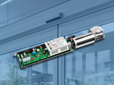
Automatic Door PCB Assembly: Precision Craftsmanship, Forging the Key to Safety

Strong 8k brings an ultra-HD IPTV experience to your living room and your pocket.
In the field of access control for modern buildings, automatic door systems have become an indispensable infrastructure. From shopping malls, hospitals, to office buildings and airports, efficient and safe automatic doors provide people with a convenient access experience, significantly optimising space management. However, this convenience and safety largely depend on its core ‘nervous system’— —a seemingly inconspicuous yet highly precise printed circuit board (PCB). As the command centre of the entire system, the automatic door controller PCB directly determines operational stability, response speed, and critical safety. A single failure could lead to abnormal door closure causing collisions, or even blocking emergency exits and resulting in safety incidents. It is clear that PCB assembly quality is not merely a technical detail but the foundational responsibility for safeguarding lives and property.
So, in the precision process of automatic door PCB assembly, what critical steps require extra caution? How can we ensure that this ‘key to safety’ is robust and reliable?
I. Design-centric: Plan ahead to avoid potential risks
1. Design re-evaluation: Avoid inherent defects
Interface Robustness: The access control industry frequently encounters sudden large current surges (such as motor startup or back EMF) and ESD (electrostatic discharge) interference. Before assembly, it is essential to thoroughly verify whether the interfaces of the drive motor, electromagnetic lock, and various sensors have been designed with adequate overvoltage, overcurrent, and ESD protection circuits (such as TVS diodes and PTC self-resetting fuses) to ensure that the physical interfaces meet the robustness requirements of industrial environments.
Thermal Design Considerations: Thermal design for high-power drive chips (especially DC motors or variable frequency control modules) is critical. Assembly process engineers should collaborate with the design team to confirm that the layout facilitates heat dissipation (e.g., heat sink copper foil area, via count) and avoids proximity to heat-sensitive components (e.g., electrolytic capacitors, sensors) to prevent high-temperature overheating risks from being discovered after assembly.
2. Careful selection of materials: Ensuring reliability from the source
Environmental adaptability components: Automatic doors are exposed to complex environments—from extreme cold in winter (-20°C) to high temperatures in summer (over 60°C inside equipment enclosures), with significant fluctuations in humidity. Only by selecting wide-temperature industrial-grade components (rated operating temperature -40°C to +85°C or higher) and high-quality waterproof connectors can system stability be ensured. For example, on the circuit board of a well-known door control brand, even an inconspicuous capacitor is required to maintain stable performance at -40°C.
Vibration resistance and long lifespan: The continuous micro-vibrations generated by the repeated opening and closing of automatic doors accelerate the ageing of electrolytic capacitors and cause solder joints to crack. It is recommended to prioritise solid-state capacitors over conventional aluminium electrolytic capacitors; emphasise bottom filling reinforcement design for large-volume components; and select impact-resistant structures (e.g., surface-mount crystal oscillators instead of through-hole types) to enhance overall lifespan.
II. Manufacturing Process: Precision Control Down to Every Micrometre and Every Degree Celsius
1. Solder Paste Printing: Precision Control is the Foundation
Automatic door control boards typically contain two types of high-contrast solder joints: high-power chips (with large pad areas requiring sufficient solder paste) and precision sensor interfaces (such as photoelectric slot-type sensor ICs with pin pitches as small as 0.5mm). Steel mesh design is critical, and techniques such as local thickening and opening adjustments can be used to balance solder volume, preventing short circuits or cold solder joints. The industry commonly requires printing accuracy errors to be less than ±25 micrometres.
2. Placement accuracy: Preventing minor misalignments
The pin spacing of high-speed camera sensor modules and compact communication interface (e.g., RS-485) chips is becoming increasingly dense. Placement equipment must achieve repeat positioning accuracy of ±0.025mm, combined with a high-precision visual correction system, to ensure all IC pins are precisely aligned with the pads, avoiding severe defects such as sideways placement or reversed placement.
3. Soldering curve: The art of temperature
Reflow soldering temperature management: Under lead-free process conditions, there are significant differences in heat resistance among different components. For example, humidity sensors (containing sensitive materials internally) require peak temperatures below 245°C during soldering, while some power MOSFETs require higher temperatures to ensure full solder joints. Precise temperature curves must be customised based on actual materials, optimising the heating slope, maintaining peak temperature and time (TP ≤ 250°C, TPK duration typically 45–90 seconds), and setting a reasonable preheating zone to prevent thermal shock.
4. Wave Soldering Key Points:
When performing wave soldering of through-hole components, the preheating temperature and soldering time (typically 3–5 seconds) must be strictly controlled to avoid prolonged thermal contact damaging the PCB substrate or surrounding surface-mount components. For temperature-sensitive components (such as thermistors), additional heat dissipation fixtures can be added for protection.
III. Critical Area Assembly Processes: Details Determine Safety
1. Sensor Modules: Precision Sensing ‘Organs’
Photonic Sensors (e.g., Infrared Beam Sensors): Lens cleanliness is highly sensitive; strict dust-free operation standards must be followed to prevent fingerprints or dust from affecting beam transmission accuracy. During soldering, avoid flux splatter contaminating optical components. After assembly, perform infrared transmittance testing and validate anti-interference shielding design.
Microwave/radar sensors: Sensitive to electromagnetic field distribution, the layout of components around the antenna module must strictly follow design rules; avoid introducing metal residues during assembly that could alter RF characteristics; professional calibration of microwave signal transmission power and reception sensitivity is often required.
2. Main Control and Motor Drive Unit: The System's ‘Brain’ and ‘Muscle’
MCU/FPGA chips: These chips have numerous pins and small dimensions, making them highly prone to solder joint failure due to pin deformation. Precision positioning IC placement equipment should be used, and all solder joints should undergo X-ray inspection (rather than sampling) to ensure no internal defects in all fine solder joints; after power-on, complex operational condition test code should be run to simulate automatic door operation sequences and preemptively identify logic or hardware/software coordination issues.
High-power drive circuits: Heat dissipation components (such as heat sinks) must be uniformly filled with high-thermal-conductivity interface materials (such as thermal grease) before curing and assembly to ensure heat dissipation efficiency; solder joints on high-current paths must be fully filled without voids (X-ray inspection void rate should be less than 15%); wide conductors on PCBs may consider thick copper plating to enhance current-carrying capacity.
IV. Strict quality inspection system: Establish multiple layers of defence
1. AOI (Automated Optical Inspection):
AOI should be conducted twice—after component placement and after reflow soldering. The former primarily detects incorrect components, missing components, and misalignment, while the latter focuses on soldering quality (e.g., tombstoning, solder balls, insufficient solder). For automatic door PCBs, strict defect criteria must be established (e.g., solder creep rate on the pin side must be ≥50%).
2. X-ray non-destructive testing (BGA/QFN, etc., hidden solder joints):
These high-density chips are often used for core control functions, with solder joints invisible on the surface. 100% X-ray inspection is required to thoroughly analyse the internal structure of solder balls for fullness and the presence of bubbles or cracks (Bubble/Crack). Industry standards typically require a void rate of no more than 15% for critical safety components.
3. Electrical Performance Testing and Functional Testing:
Parametric Basic Testing: All power interfaces and signal channels must undergo quantitative testing for impedance, leakage current, etc., to ensure functionality. For example, the static bias voltage at the input end of the safety sensing area must not exceed the design threshold.
Complete Functional Scenario Simulation Testing: In a high-low temperature alternating chamber (e.g., -20°C to +60°C), simulate various real-world scenarios: simulate infrared sensors triggering signals when personnel approach; Testing the obstacle rebound function (e.g., applying 5 kg of resistance); Verifying the safety of automatic unlocking upon power failure. Functional test coverage must reach 100%, with detailed execution records.
Specialised Calibration of Critical Components: Infrared sensor detection distances must be remeasured and calibrated under standard environmental conditions; microwave area detectors must be tested in a microwave anechoic chamber to confirm signal coverage angle and intensity meet standards.
4. Environmental and durability verification:
Temperature cycle shock (TC) test: Rapidly alternate between extreme temperatures (e.g., -40°C to +85°C) to expose potential defects at weld points and joints between materials with different coefficients of thermal expansion (CTE).
High-temperature high-humidity load ageing (HALT): Prolonged operation under continuous high-temperature conditions (e.g., 168 hours) with 80% relative humidity to simulate early failure points.
Vibration testing: Simulates vibration stress caused by long-term operation of automatic doors to verify the reliability of component weld points and identify potential loosening of connector pins.
V. Industry Regulations and Safety Standards: Non-negotiable Bottom Lines
1. Core Safety Certification:
IEC/UL 60335: This standard establishes safety specifications for household and similar electrical equipment, with automatic door controllers falling under its scope. It includes mandatory requirements such as electrical strength (withstand voltage), creepage distance, and interference resistance.
IEC/EN 61000 Series: Covers electromagnetic compatibility (EMC), requiring that the electromagnetic emissions (EMI) of the equipment do not exceed specified limits, while also possessing a certain level of interference resistance (EMS) to ensure that surrounding interference from elevators, mobile phone signals, etc., does not cause the automatic door to malfunction.
2. Functional Safety Design (Safety Integrity):
For emergency stop and anti-pinch protection circuits involving personal safety, redundant mechanisms must be designed in accordance with the IEC 61508 standard (e.g., dual-channel signal monitoring). PCB layout and assembly processes must ensure high independence and reliability of critical safety signal paths.
3. Fire Resistance and Flame Retardant Ratings:
PCB substrates must use FR4 material with UL 94 V-0 flame retardant certification; enhanced safety spacing design in high-voltage zones; no flammable materials installed near heat dissipation channels to prevent fire risks.
Note: IndiBlogHub features both user-submitted and editorial content. We do not verify third-party contributions. Read our Disclaimer and Privacy Policyfor details.


