
What Is a Rebar Placing Drawing?
-

- September 26th, 2026
- 91 views
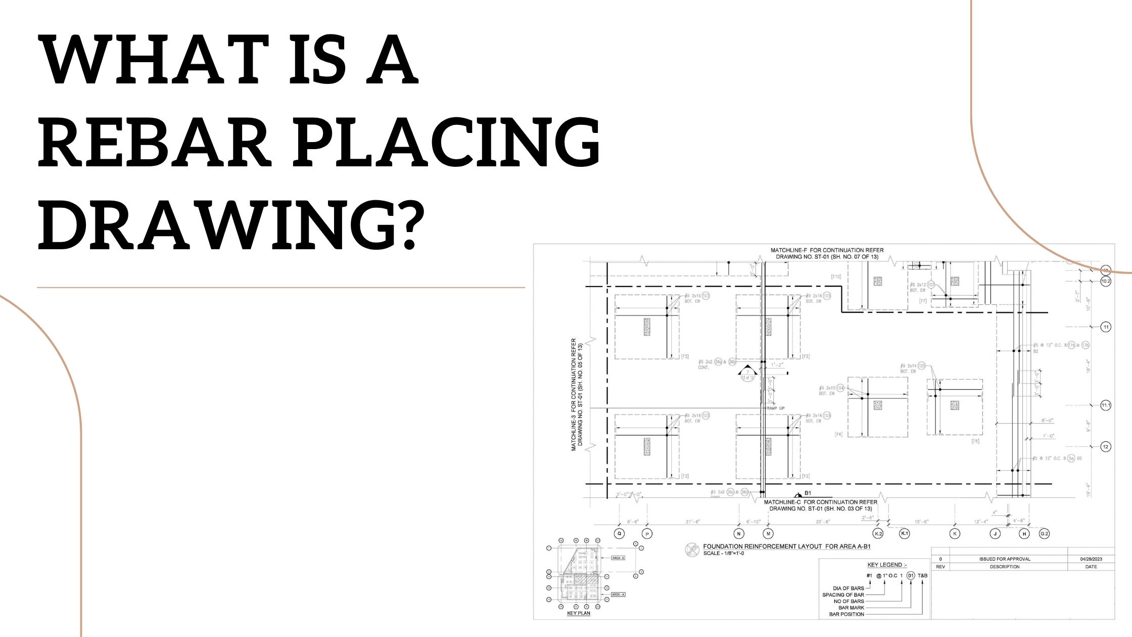
A rebar placing drawing gives the construction team a clear view of how reinforcing steel needs to be arranged within a concrete structure. For engineers, builders, detailers, BIM modelers, and drafters, it connects structural design information with the actual placement of reinforcement. As part of Rebar Shop Drawings Services, these drawings translate structural requirements into detailed information that can be followed during reinforcement fabrication and installation.
Understanding Rebar Placing Drawings
A rebar placing drawing is a detailed construction drawing that shows the location, arrangement, size, spacing, shape, and identification of reinforcing bars within concrete members. It is developed from structural drawings, engineering notes, design specifications, schedules, and project requirements.
The drawing may cover slabs, beams, columns, walls, footings, foundations, retaining walls, stairs, pile caps, and other reinforced concrete elements. Instead of showing only the overall structural form, it focuses on the reinforcement that needs to be placed inside each member.
This distinction is important because structural drawings communicate the engineer's design intent, while placing drawings provide the detailed reinforcement information needed to translate that intent into construction work.
What Information Does a Rebar Placing Drawing Contain?
The information shown in a placing drawing depends on the structural member and project requirements. A typical drawing identifies reinforcement through bar marks and provides information such as bar diameter, spacing, quantity, length, shape, location, and direction.
Dimensions are used to establish where reinforcement begins and ends, while sections and enlarged views can clarify areas where several bars intersect. Details may also show laps, hooks, bends, development lengths, anchorage, concrete cover, and reinforcement around openings.
Bar marks provide an important connection between the drawing and the related bar schedule. When a worker or fabricator identifies a bar mark on the placing drawing, the corresponding schedule can provide additional information about that particular bar.
How Rebar Placing Drawings Are Developed
The preparation process begins with a detailed review of the available structural information. A detailer studies plans, sections, elevations, structural notes, reinforcement schedules, specifications, and revisions before developing the reinforcement layout.
The structural members are then reviewed individually and in relation to connected elements. Reinforcement is arranged according to the design requirements, while dimensions, spacing, bar marks, and other information are added to the drawing.
The work becomes more involved around beam-column connections, slab openings, wall intersections, foundations, construction joints, and other areas where several reinforcement requirements meet. These locations require careful interpretation because the drawing must communicate how the reinforcement is arranged within the available structural space.
This is where Rebar Detailing Services become particularly useful. The detailing process converts engineering information into a drawing that can be understood by the people responsible for reinforcement fabrication and placement.
Difference Between Structural Drawings and Rebar Placing Drawings
Structural drawings and rebar placing drawings are closely connected, but they do not serve exactly the same purpose. A structural drawing primarily communicates the design and dimensions of the structural system. It identifies members such as beams, columns, slabs, walls, and foundations along with their required structural information.
A placing drawing goes further into the reinforcement arrangement. It identifies individual reinforcement bars and communicates their position, spacing, shape, and relationship with the surrounding concrete member.
For example, a structural drawing may indicate the reinforcement requirement for a beam, while the placing drawing can show the individual bars, their marks, spacing, bends, laps, and sectional arrangement. This level of information makes the drawing more useful during reinforcement work.
Role of Rebar Placing Drawings in Construction
Reinforcing steel is installed before concrete is poured, which means the placement needs to be understood before the reinforcement becomes hidden inside the finished member. A clear placing drawing provides a common reference for engineers, detailers, fabricators, contractors, and reinforcement workers.
The drawing can also help identify areas that require closer review before construction progresses. When reinforcement from different structural members meets in a confined area, the drawing provides an opportunity to examine the arrangement and communicate the required details.
For larger projects, consistent Rebar Drawings can also make it easier to manage reinforcement information across different structural areas and drawing revisions.
Rebar Placing Drawings and BIM
BIM has added another dimension to reinforcement detailing. Instead of working only with two-dimensional views, detailers can develop reinforcement within a three-dimensional structural model.
A BIM model allows reinforcement to be viewed in relation to beams, columns, slabs, walls, openings, and other elements. This can make complicated reinforcement arrangements easier to review before drawings are issued.
The model can also support the generation of drawing views, bar schedules, and reinforcement documentation. However, the software itself does not determine the correct reinforcement arrangement. The person developing the model still needs to interpret the structural information and apply the project's requirements correctly.
Common Issues That Affect Rebar Placing Drawings
A placing drawing can become difficult to use when important information is missing or presented inconsistently. Unclear bar marks, incomplete dimensions, conflicting spacing information, outdated revisions, and crowded annotations can make reinforcement interpretation harder.
Complex intersections are another area that deserves attention. Reinforcement from beams, slabs, columns, and walls may occupy the same region, and a simple plan view may not communicate the arrangement clearly. Sections and enlarged details can provide additional information where the main view is not sufficient.
Revision control is equally important. Structural designs can change during a project, and placing drawings need to reflect the applicable design information. Using an outdated drawing can result in reinforcement being fabricated or placed according to superseded requirements.
Why Clear Placing Drawings Matter to Professionals
For engineers, a well-developed placing drawing provides a detailed representation of how the reinforcement design has been interpreted. For builders and contractors, it provides information that can be referenced during reinforcement work. For fabricators, the connection between bar marks, shapes, lengths, and schedules supports the preparation of reinforcement bars.
For detailers and BIM modelers, the drawing is also the final communication layer between the structural model or design information and the people using that information during construction.
This is why Rebar Services involve more than simply drawing reinforcement lines. The work requires an understanding of structural geometry, reinforcement requirements, drawing conventions, dimensions, schedules, and the practical conditions in which the documentation will be used.