Why Stainless Steel Parts Distort During CNC Machining
-

- Published Updated
- 40 views
A stainless steel component may meet its dimensions while clamped inside a machine and still change shape after release. A thin plate can bow, a precision bore can become oval, or a long shaft can lose straightness after material is removed. These problems are often blamed on machine accuracy, yet the real causes usually extend across the entire manufacturing system. Material history, residual stress, cutting heat, work hardening, tool wear, clamping pressure, and inspection conditions can all influence the final geometry. Reliable stainless steel CNC machining therefore requires more than an accurate tool path. Engineers must understand when the material is likely to move, how the fixture may temporarily conceal that movement, and which controls can maintain dimensional stability after the finished part is removed from the machine.
Stainless Steel Distortion Begins Before Machining
Stainless steel stock is not necessarily stress-free when it arrives at a machine shop. Rolling, drawing, forging, heat treatment, straightening, and thermal cutting can leave internal stresses in the material. These forces may remain balanced while the stock retains its original shape.
Machining disturbs that balance. When material is removed from one area, the remaining stresses redistribute through the part. The component may bend, twist, or change size even when the CNC program follows the drawing correctly.
| Material condition | Possible result after machining |
| Cold-drawn bar | Straightness changes after heavy material removal |
| Rolled plate | The part bows after one face is machined |
| Forged blank | Uneven movement appears as the internal structure is exposed |
| Laser-cut blank | Thermally affected edges influence flatness |
| Previously straightened stock | The original curvature partially returns |
The severity of residual stress in stainless steel depends on the material form, production history, thickness, alloy, and amount of stock removed. Two visually identical bars from different production batches may not respond in exactly the same way.
This is why incoming material condition matters for precision work. Specifying only the alloy grade may be insufficient when a part has thin sections, long unsupported lengths, demanding flatness, or extensive material removal.
Cutting Heat and Work Hardening Increase Dimensional Variation
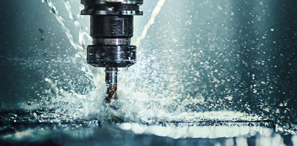
Stainless steel retains more cutting heat near the tool and workpiece interface than highly conductive metals such as aluminum. The resulting local temperature rise affects tool life, surface quality, and the dimensions observed during machining.
Heat is not the only concern. Austenitic grades such as 304 and 316 can harden rapidly when the cutting edge rubs instead of removing a stable chip. Heat and work hardening can then reinforce each other: cutting becomes more difficult, forces rise, and the part deflects further.
Local Heat Changes the Part During Measurement
Every material expands as its temperature rises. If a precision feature is measured immediately after a heavy cutting operation, its warm dimension may not represent its final dimension at room temperature.
This is especially relevant for:
- Thin plates with broad machined faces
- Long shafts and rails
- Deep pockets surrounded by thin walls
- Parts requiring close bore-to-bore relationships
- Components with strict flatness or parallelism requirements
Local heating is more problematic than a uniform temperature rise because one region expands while another remains relatively cool. The resulting temperature gradient can temporarily bend the component.
Coolant delivery, chip evacuation, cutting engagement, and tool condition all influence heat distortion during machining. A worn cutter generates more friction, while trapped chips can repeatedly contact the surface and introduce additional heat.
Critical measurements should therefore be taken after the component reaches a stable temperature. For demanding parts, the raw material, machine environment, inspection area, and measurement equipment may also require temperature control.
Work-Hardened Surfaces Raise Cutting Forces
Stainless steel work hardening occurs when the surface is plastically deformed during cutting. If the tool rubs, dwells, or takes an excessively light cut, the next pass may encounter a harder layer than the original material.
The harder surface increases cutting pressure and can produce several secondary problems:
- Greater deflection in thin walls
- Faster tool wear
- Larger burrs
- Inconsistent surface finish
- Increased heat generation
- Sudden tool-edge failure
Reducing feed too aggressively does not always make the operation safer. If the cutting edge fails to maintain an effective chip load, it may rub against the material and worsen the hardened layer.
Sharp tooling, stable engagement, suitable feeds, and continuous chip formation are usually more important than simply running the machine slowly. Once severe work hardening develops, the damaged surface may need to be removed with a sufficiently positive and stable cut.
Clamping Can Hide Distortion Until the Part Is Released
A fixture does more than hold a component against cutting forces. It can also force an unstable blank into a temporary shape. The machine then cuts that restrained shape accurately, but the part moves when the clamping force is removed.
A common example occurs when a slightly bowed plate is pulled flat against a fixture. The machined face appears flat during the operation. After release, the plate returns toward its original curvature, and the newly machined surface no longer meets the intended flatness.
Other characteristic symptoms include:
- A bore becomes smaller or oval after the chuck is released.
- A thin ring develops a three-lobed shape after three-jaw clamping.
- A housing wall springs inward after internal machining.
- Hole positions shift because a flexible bracket was forced against locating stops.
- Different operators obtain different results because they apply different clamping pressure.
Fixtures for thin-wall stainless steel machining should distribute force across stable regions. Adjustable pneumatic or hydraulic pressure can improve repeatability, but controlled force alone does not solve an unsuitable locating strategy.
The cutting direction also matters. A fixture that resists force well in one direction may allow movement when another face is machined. Supporting the workpiece close to the cutting zone can reduce deflection, provided the support does not over-constrain the component.
In some cases, machining jaws or fixture contacts to match the part geometry is more effective than applying additional force. The objective is stable support with the least distortion necessary to resist cutting.
Thin Walls and Uneven Geometry Are Less Dimensionally Stable
Final wall thickness is only one measure of distortion risk. The proportion and location of removed material can be equally important.
Consider a shallow housing machined from thick plate. The finished base may not appear unusually thin, but producing it requires removing a large volume of material from one side. That asymmetric removal releases internal stress unevenly and changes the stiffness of the blank throughout the operation.
High-risk forms include:
- Wide parts with thin bottom sections
- Tall walls around deep cavities
- Thin sleeves and rings
- Long shafts with flats or deep slots on one side
- Brackets with heavily offset features
- Components with sudden transitions between thick and thin regions
Stiffness falls rapidly as a wall becomes thinner. A cutting force that has little effect during roughing can deflect the same feature during the final passes after most supporting material has disappeared.
Tool access can make the problem worse. A long-reach cutter used inside a deep pocket adds its own deflection and vibration. The resulting error comes from the combined movement of the tool and workpiece, not from either one alone.
Design changes can sometimes improve stability without changing the component’s function. More uniform walls, larger internal radii, supportive ribs, and reduced pocket depth may all improve machinability. Where geometry cannot change, the process must use controlled stock allowance, suitable support, and lighter finishing loads.
304 and 316 Stainless Steel Behave Differently in Machining
The description “stainless steel” covers many alloys with different mechanical and machining characteristics. Even widely used grades should not be treated as interchangeable.
When machining 304 stainless steel, engineers must account for its tendency to work-harden, produce difficult chips, and build heat near the cutting edge. Maintaining a positive cutting action is essential.
When machining 316 stainless steel, the added molybdenum improves corrosion performance but can contribute to higher cutting resistance and faster tool wear. Stable tooling and effective coolant application become particularly important on long production runs.
Engineers comparing alloy behaviour, tooling requirements, and achievable component features can review these stainless steel CNC machining considerations before finalising the material and drawing.
Material condition matters alongside grade. Annealed stock, cold-worked bar, rolled plate, and hardened stainless steel can behave differently even when the basic alloy designation is similar. Procurement documents should therefore identify the required form and condition rather than specifying only “304” or “316.”
Free-machining stainless grades can shorten cycle times and improve chip control, but they are not universal replacements. Their corrosion performance, weldability, regulatory acceptability, or mechanical properties may not suit the application. Machinability must remain one factor within the overall material decision.
Tool Wear Produces Gradual Dimensional Drift
Tool wear does not always cause an immediate failure. It can create a slow change that remains unnoticed until measurements approach or cross the tolerance limit.
As the cutting edge wears, cutting force usually increases. A rigid component may experience a predictable size change, while a flexible wall or long shaft may deflect more severely. The same tool wear can therefore produce different dimensional effects across one part.
Warning signals include:
- Increasing spindle load
- Larger or more difficult burrs
- Changing chip colour and form
- Loss of surface brightness
- Growing vibration or noise
- A critical dimension trending consistently in one direction
Tool wear in stainless steel machining can also increase stainless steel burr formation. Burr growth is not merely a cosmetic issue. A burr may affect assembly, interfere with measurement, damage seals, or require manual removal that changes an edge.
Replacing a tool only after a part becomes nonconforming is a reactive strategy. Repeat production benefits from defined tool-life limits, dimensional trend monitoring, and planned replacement before the cutting edge becomes unstable.
Tool offsets can compensate for predictable dimensional change, but they cannot correct every problem. Compensation will not eliminate chatter, restore a damaged edge, or reduce the additional force acting on a thin feature.
Roughing and Finishing Have Different Engineering Objectives
Roughing removes material efficiently and exposes how the blank responds to stress release. Finishing establishes the final size, form, and surface. Combining both objectives without adequate stock planning can leave too little material to correct movement.
For distortion-sensitive machined stainless steel components, roughing should leave a controlled and reasonably uniform allowance on critical surfaces. If one region contains much more stock than another, the finishing forces and heat exposure may remain unbalanced.
The part may also benefit from being released and relocated between roughing and finishing. This allows some movement to occur before the final features are produced. For particularly demanding components, an intermediate stabilisation or stress-relief machining strategy may be appropriate.
The exact approach depends on the geometry and material history. It may involve:
- Balanced material removal from opposing faces
- Separate roughing and finishing setups
- Re-establishing datums after stress release
- Leaving support features temporarily in place
- Allowing the component to cool before final measurement
- Using lighter finishing cuts with sharp tooling
There is no single sequence suitable for every stainless steel part. A thin plate, deep housing, precision ring, and long shaft require different ways of managing movement.
Inspection Must Reflect the Part’s Functional State
Measurement results depend on how the part is supported, restrained, and conditioned. A flexible component measured under clamp pressure may appear compliant even though it will not meet its requirement in the free state.
A drawing with a stainless steel flatness tolerance should make clear whether the requirement applies freely, under specified restraint, or after assembly. Without that distinction, the buyer and manufacturer may evaluate the same part differently.
Inspection should consider:
- Whether the component has cooled to a stable temperature
- Whether burrs or contamination affect contact points
- How the part is supported during measurement
- Whether measuring force deforms a thin feature
- Whether the datum setup represents actual assembly
- Whether final finishing changes the measured surface
A coordinate measuring machine can report detailed geometric data, but it cannot resolve an unclear functional requirement. The inspection setup must represent how the feature is intended to locate, move, or assemble.
Where possible, production measurements should also track trends rather than record only pass-or-fail results. Gradual movement can reveal tool wear, fixture changes, or material variation before rejected parts accumulate.
Stable Stainless Steel Parts Require Control of the Whole System
Stainless steel machining distortion is rarely caused by a single mistake. Internal material stress may initiate movement, while cutting heat, work hardening, tool wear, or clamping pressure adds further variation. Inspection can then conceal or exaggerate the result if temperature and support conditions are not controlled.
Stable production begins with the correct stainless grade and material condition. It continues through balanced stock removal, appropriate workholding, sharp tools, planned tool-life limits, and finishing operations that allow the part to settle before final measurement.
Designers can also help by avoiding unnecessarily thin or uneven sections and by identifying whether geometric requirements apply in a free or assembled state. When material, geometry, machining, fixturing, and inspection are treated as one connected system, stainless steel parts are far more likely to retain their intended dimensions after leaving the machine.