Design & Applications of Carbon Steel Floating Pipeline Systems Using LSAW and SSAW Pipes
-
- February 28th, 2026
- 311 views

Get a free topical map and start building content authority today.
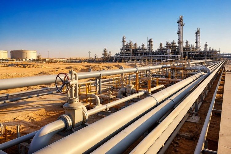
Carbon steel floating pipeline systems are an established option for transferring hydrocarbons, produced water, and power cables in shallow-to-mid water depths. This guide explains how Longitudinal Submerged Arc Welding (LSAW) and Spiral Submerged Arc Welding (SSAW) steel pipes are used in floating and semi-floating pipeline arrangements, and which design and operational controls reduce fatigue, corrosion, and installation risk.
- Scope: How LSAW and SSAW large-diameter submerged arc welded pipes perform in floating, buoyant, and moored pipeline layouts.
- Key risks: fatigue from wave-induced motion, corrosion, weld quality, and hydrodynamic loading.
- Framework: FLOT-Pipe Checklist (Feasibility, Loading, Offloading, Tensioning, Protection — Pipeline Integrity, Execution).
- Detected intent: Informational
- Core cluster questions:
- How do LSAW and SSAW pipe manufacturing differences affect pipeline fatigue life?
- What corrosion protection is needed for floating steel pipelines in marine environments?
- When is a buoyant pipeline preferable to a catenary riser or SPAR connection?
- How are dynamic loads modeled for moored floating pipelines?
- What installation methods are used for large-diameter submerged arc welded pipes offshore?
carbon steel floating pipeline systems: basic concepts and where LSAW/SSAW fit
LSAW (Longitudinal Submerged Arc Welding) and SSAW (Spiral Submerged Arc Welding) are two manufacturing methods for steel pipes commonly produced to API 5L and similar specifications. In floating pipeline systems they are chosen when large diameters and cost-effective long-length delivery are required. Key differences in geometry and seam orientation influence bending stiffness, fatigue crack propagation, and ease of coating.
Manufacturing and mechanical differences: LSAW vs SSAW
What LSAW and SSAW mean
LSAW pipes are built from plate rolled and welded along a longitudinal seam; SSAW pipes are formed by spirally winding steel strip with a helix seam. LSAW typically yields a straighter pipe with a longitudinal seam that is easier to inspect along axial direction. SSAW produces long continuous lengths with circumferential seam angles that alter local stress directions under bending.
Performance trade-offs
- Fatigue: LSAW seams run axially, which can be advantageous for axial fatigue but requires careful root- and heat-affected-zone control. SSAW seams introduce angled welds that can change crack initiation orientation under cyclic bending.
- Manufacturing length and cost: SSAW permits very long continuous lengths and often lower production cost for very large diameters; LSAW is favored where plate quality and seam inspection are prioritized.
- Coating and lining: Both accept standard external coatings (FBE, three-layer polyethylene) and internal linings; seam geometry affects coating application and holiday testing strategies.
Typical floating pipeline system types and where these pipes are used
Buoyant pipeline with modular flotation
Pipelines supported by discrete buoyancy modules along their length reduce seabed contact and are suited to relatively calm waters and shallow depths. LSAW/SSAW pipes are used when a high flow capacity is needed; connection details must account for module clamping loads and local stresses.
Catenary and riser-connected floating systems
Catenary risers and flexible riser tie-ins are used when connecting floating production units to seabed facilities. Steel submerged-arc welded pipes can be used for the near-surface spans where stiffness is needed; expansion joints or flexible sections absorb relative motion.
FLOT-Pipe Checklist: a practical framework for early-stage decisions
The FLOT-Pipe Checklist consolidates the critical design stages that repeatedly determine project success.
- Feasibility — site environmental data, soil and bathymetry, service life target.
- Loading — hydrodynamic loading, wave/current spectra, vessel interaction, surge and wind inputs.
- Offloading/connection — tie-in method, leak detection, pigging and maintenance strategy.
- Tensioning — mooring and tension control, buoyancy distribution, slack allowances.
- Protection — corrosion control (cathodic protection, coatings), mechanical protection (rock dumping, mattress), inspection plan.
- Pipeline Integrity & Execution — NDT welding procedures, QA/QC, fatigue and fracture mechanics assessments, installation sequencing.
Key design considerations: fatigue, corrosion, and installation
Fatigue and dynamic analysis
Fatigue life prediction requires time-domain or frequency-domain assessment of wave-induced bending and axial loads, accounting for seam orientation (LSAW vs SSAW) and local weld detail. Use fracture mechanics methods consistent with industry practice; many projects follow DNV and API guidance for pipeline fatigue assessment. DNV publishes recommended practices used widely in industry.
Corrosion protection
External coatings, sacrificial anodes or impressed current cathodic protection, and internal inhibitors are typical. Coating selection must consider flexing points and module clamping; holiday testing and coating repair plans are essential for inspection-based maintenance.
Installation and handling
Installation options include reel-lay for flexible sections, float-over or S-lay for rigid joints, and end-to-end welding at seabed or on barges. Lifting and S-lay bending radii must respect pipe yield strength and seam properties to avoid cold bending damage or inducing weld defects.
Real-world example scenario
Scenario: A 24-inch production line (600 mm OD) connects a floating storage and offloading unit (FSO) to a nearshore processing hub over 12 km in 15–30 m water depth. SSAW pipe was selected for long welded lengths delivered to the project staging yard. Buoyancy modules were installed every 20 m to achieve neutral buoyancy, reducing contact with the seabed and lowering in-service wave-induced fatigue. Design used the FLOT-Pipe Checklist: hydrodynamic loads were modeled with time-domain simulations, sacrificial anodes were sized per current density estimates, and a weld inspection program was implemented using phased-array ultrasonic testing. The resulting layout balanced manufacturing cost and fatigue life by choosing thicker wall SSAW with enhanced post-weld heat treatment at seam areas identified as high stress.
Practical tips for engineers and asset owners
- Model dynamic behaviour with site-specific wave spectra and include vessel interaction for moored systems.
- Specify weld procedures that control HAZ toughness and require post-weld NDT on high-stress seams.
- Design buoyancy spacing to limit mid-span curvature and reduce local bending stresses at seam locations.
- Plan for in-service inspection access and include pigging and leak detection capabilities from the outset.
- Document coating holiday testing and repair criteria tailored to bend regions and clamp points.
Common mistakes and trade-offs
- Underestimating dynamic motions: omitting vessel interactions or second-order drift can under-predict fatigue damage.
- Ignoring seam orientation effects: treating LSAW and SSAW as identical in fatigue models leads to conservative or unsafe designs.
- Over-reliance on coatings without CP: coatings can fail; cathodic protection and inspection are needed for long-term integrity.
- Choosing cost only: lowest-cost pipe or shorter QA schedules often increase lifecycle maintenance and failure risk.
Standards and verification
Reference applicable standards early: API 5L for pipe material properties and DNV recommended practices for offshore pipeline integrity and fatigue assessment. Independent third-party inspection for weld quality and fatigue-critical details is a best practice for high-consequence projects.
Implementation checklist (quick)
- Site survey and environmental data collection
- Material selection: LSAW vs SSAW based on length, diameter, seam impact
- Fatigue and fracture mechanics analysis
- Coating and cathodic protection design
- Welding procedure & NDT plan
- Installation method and contingency planning
- Inspection, pigging, and maintenance scheduling
FAQ
What are the advantages of carbon steel floating pipeline systems compared to flexible or composite lines?
Carbon steel pipelines provide higher strength and often lower unit cost for large diameters, are easier to pig and inspect mechanically, and accept standard coatings and cathodic protection. They require more attention to fatigue and corrosion in moving environments than flexible or composite alternatives.
How do LSAW and SSAW pipe manufacturing differences affect pipeline fatigue life?
Seam orientation alters local stress fields: LSAW axial seams can be favorable for axial load distribution, while SSAW angled seams change crack propagation direction under bending. Fatigue life depends on seam toe detail, HAZ toughness, and coating integrity; design analyses must model seam geometry and local stress concentrations.
What corrosion protection strategies are recommended for floating steel pipelines?
Combine robust external coatings with cathodic protection (sacrificial anodes or impressed current), internal corrosion inhibitors where applicable, and an inspection program. Coating selection should account for flex zones and clamp locations.
How should dynamic loads for moored floating pipelines be modeled?
Use time-domain simulations with realistic wave, current, and wind inputs, include vessel and mooring interactions, and validate models with physical or scaled tests when possible. Follow accepted practices from standards bodies for input spectra and fatigue analysis.
What maintenance and inspection protocols are essential for long-term operation of carbon steel floating pipeline systems?
Regular pigging, scheduled CP surveys, offshore holiday testing of coatings, visual/ROV inspections at support and clamp points, and periodic fitness-for-service assessments based on recorded load cycles and inspection data are essential for maintaining integrity.