Copper SFP Modules: Cost-Effective High-Speed Ethernet for Data Centers
-

- March 23rd, 2026
- 289 views

Get a free topical map and start building content authority today.
Copper SFP modules provide an economical, low-latency option for short-reach Ethernet links inside racks and between adjacent switches. This guide explains how a copper SFP module works, when it is the right choice, compatibility considerations, and practical steps to deploy and troubleshoot them in production networks.
Detected intent: Informational
Quick takeaways: copper SFP modules are small form-factor pluggable transceivers that terminate RJ45 copper or use twinax copper cables, offering lower cost and power than fiber for short distances (typically up to 30 m for SFP+ copper twinax, longer for RJ45 1G). Use them for server-to-top-of-rack links, switch stacking, and lab/test environments. Consider compatibility, port speed, and cable type before buying.
Core cluster questions (use for internal links):
- What is a copper SFP and how does it work?
- When should copper SFPs be used instead of fiber optics?
- How to choose the right copper SFP for 1G, 10G, or 25G networks?
- What compatibility and distance limits apply to copper SFP connections?
- How to troubleshoot common link problems with copper SFP modules?
Copper SFP module: what it is and when to use it
Definition and types
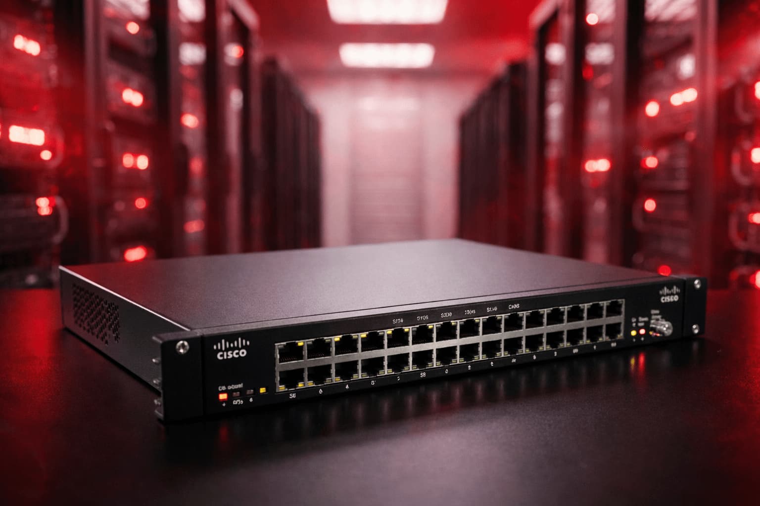
A copper SFP module is a hot-swappable transceiver that fits into an SFP or SFP+ port and supports electrical (copper) interfaces instead of optical fiber. Types include RJ45 SFP for twisted-pair copper (common at 1 Gbps) and direct-attach copper (DAC) or twinax SFP+ for short 10 Gbps links. These modules implement the physical-layer requirements defined by Ethernet standards and SFP/SFP+ MSA specifications.
When to choose copper over fiber
- Short-distance links within racks or adjacent racks (savings on optics and fiber installation)
- Lower latency and power consumption needs
- Temporary lab setups or testing environments where cost and speed-to-deploy matter
Benefits, limitations, and compatibility
Key benefits
- Lower upfront cost per port compared with optical transceivers plus fiber cabling
- Simpler cabling for short runs—no fiber patch panels or specialized cleaning
- Lower power and very low link latency, useful for high-performance computing pairs
Common limitations and distance limits
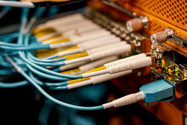
Distance and performance depend on the specific copper interface: RJ45 SFPs typically support 100 meters at 1 Gbps over Cat5e/6; 10G RJ45 SFP+ over copper is possible but power-hungry and limited in distance. SFP+ direct-attach copper (DAC) twinax cables are typically limited to 1–7 meters for passive and up to 15 meters for active designs. For longer runs or electromagnetic immunity, fiber remains the better option.
Compatibility checklist
Vendor compatibility is the most common source of deployment problems. Match the following:
- Port speed (1G, 10G, etc.) with the module and cable type
- Switch/router vendor and model — check supported SFP/SFP+ part numbers and firmware
- Electrical interface (RJ45 vs. DAC/twinax) and connector type
- Power and thermal limits for the device and module
Deployment framework: the CABLE Checklist
Use the CABLE Checklist to evaluate copper SFP module suitability:
- Compatibility — Verify switch/port support and firmware.
- Application — Confirm whether link requirements are server uplink, switch stacking, or access layer.
- Bandwidth — Ensure module matches required throughput (1G/10G).
- Length — Measure expected cable runs vs. module/cable limits.
- Economics — Compare total cost of ownership (module + cabling + power) vs. fiber.
Practical deployment steps and tips
Step-by-step actions
- Define the link: document endpoints, required speed, and exact rack locations.
- Choose interface: RJ45 for up to 1G over structured cabling, twinax DAC or active cable for short 10G links.
- Check vendor compatibility and test one link in the lab before bulk deployment.
- Install module and cable, verify link status and error counters, and monitor over the first 72 hours.
Practical tips
- Always check switch logs for mismatch or negotiation errors after insertion.
- Use labeled cables and record cable lengths—this prevents accidental replacement with incompatible types.
- Reserve RJ45 SFPs for up to 1 Gbps or when structured cabling exists; use DAC/twinax for predictable short 10 Gbps links to reduce jitter.
- Keep spare modules of the same vendor/model in the maintenance kit to speed recovery.
Trade-offs and common mistakes
Trade-offs
Copper SFP modules reduce cost and latency for short links but sacrifice reach and electromagnetic isolation compared with fiber. Power consumption can be higher for RJ45 10G solutions, and DAC cables limit physical flexibility compared to separate transceivers and fiber patch cords.
Common mistakes to avoid
- Assuming every SFP port accepts every third-party copper module—firmware and vendor lockouts can block operation.
- Using DAC/twinax beyond its designed length, which can produce intermittent errors hard to diagnose.
- Not testing in the target environment—thermal and power differences affect real-world behavior.
Real-world example scenario
A small data center needs 10 Gbps links between two top-of-rack switches separated by 3 meters. Fiber installation would require patching panels and splicing; using passive SFP+ direct-attach copper twinax cables and matching SFP+ copper modules delivers the required bandwidth, lowers total cost by avoiding fiber panels, and reduces latency. Before rolling out, one link is validated in a staging rack using the CABLE Checklist: compatibility verified, length measured, and power budget confirmed. Monitoring shows stable throughput and no error counters after 72 hours, so the same approach is applied to the remaining racks.
Troubleshooting quick reference
Common diagnostics
- Link down: check physical seating, port configuration (speed/duplex/autoneg), and port status LEDs.
- High error counts: swap the cable, check for electromagnetic interference, and verify cable length vs. spec.
- Intermittent flaps: confirm firmware compatibility and power/thermal constraints on the switch.
Standards bodies define the Ethernet physical and MAC layer behaviors that copper SFPs implement—see the IEEE 802.3 Ethernet standards for formal definitions and signaling behavior: IEEE 802.3.
When to pick fiber instead
Choose fiber when runs exceed copper limits, when isolation from electromagnetic interference is required, or when future-proofing for higher speeds and longer distances is a priority. Fiber optics also simplify long-term cabling management in campus and metro deployments.
FAQ
What is a copper SFP module and how does it differ from optic modules?
A copper SFP module uses an electrical interface (RJ45 or twinax) to send Ethernet signals over copper cable, unlike optical SFPs that use lasers and fiber. Copper is cheaper and lower-latency for short links but limited in distance and EMI resilience.
Are 10G SFP copper options reliable for production networks?
Yes, for short runs such as within a rack or adjacent racks. Use passive DACs for very short distances (1–3 m) and active twinax for slightly longer runs. Confirm the switch vendor supports the exact module and cable type; test before wide deployment.
How to check SFP copper compatibility with network equipment?
Review the switch or server hardware compatibility list (HCL) and product documentation. Check port speeds, supported vendor part numbers, and firmware notes. If unsure, test a single link in the lab or staging environment before buying in quantity.
What are the typical distance limits for RJ45 and DAC copper SFPs?
RJ45 SFPs over Cat5e/Cat6 typically support up to 100 meters at 1 Gbps. SFP+ DAC/twinax cables are typically limited to 1–7 meters for passive designs and up to ~15 meters for active variants. Exact limits depend on cable construction and module specifications.
How to troubleshoot link flaps or errors with a copper SFP module?
Start by reseating the module and replacing the cable to isolate hardware issues. Check port configuration and firmware levels; use the switch's diagnostic counters to look for CRC or alignment errors. If problems persist, test with a known-good module and cable and review thermal/power conditions on the device.